 Spatial Understanding Tutorial
An MRTK Solver Guide, with Examples
Contents
- Overview
- Setting the Scene
- Spatial Understanding
- Mixed Reality Toolkit Solvers
- InBetween and Momentum - Building a Catapult
- Final Words
Overview
In this tutorial I will give you an overview of spatial understanding, demonstrate the use of solvers and show how we can use these to control the way object behave in the playspace. There are four scenes, each with a corresponding prefab that provide example applications for orbital, radial view, surface magnetism solvers and, finally, a combination of several solvers to build a catapult.
By the end of the tutorial, you should understand:
- What are solvers?
- What types of solvers exist in the MRTK (2.3) API?
- What are the benefits and constraints of working with each type?
- How can you implement them in your Unity project?
In this document, terms marked with italics are keywords that are searchable in unity and online. It is helpful to go through the steps.
Setting the Scene
Software versions: Unity 2018.4.20, MRTK 2.3.0, Visual Studio 2019
This tutorial assumes that you have an active Unity project, with Mixed Reality Toolkit loaded in to the scene, as described here and configured for the HoloLens 2. We will use the emulator, so you don’t need lengthy deployments / device sharing. Documentation for the emulator is found here.
The MRTK files are available in the course’s file storage and from Microsoft. We will be using just the Foundation package for now, but others are available (Extensions, Tools, Examples).
The first thing to do is set up the Mixed Reality Toolkit system which, after importing the above packages, is most easily done through the toolbar entry Mixed Reality Toolkit > Add to scene and configure, and selecting the option ‘Create New Profiles’ on the newly created ToolkitConfigurator option. If you don’t see it in the inspector, it is found under:
Assets / MixedRealityToolkit.Generated / CustomProfiles
We will use the ‘DefaultMixedReality[…]Profile’ options, on the following:
- Camera system
- Input system
- Spatial Awareness system
Once this is done, go to the build settings and make sure that UWP is targeted. Select HoloLens as the targeted device. If you are building for the HoloLens 2 or the emulator, you can use a 64-bit (x64). If it’s a first gen. headset, use x86.
The scripting backend can be either IL2CPP or .NET - there are advantages to both, which I won’t cover here, .NET can speed up development but has quirks. For better or worse, this tutorial will use .NET.
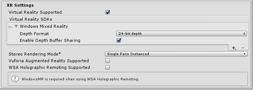
If you are missing any of the needed capabilities, they should be added automatically. If they are not, head to the player settings and include them there (InternetClient, Microphone and SpatialPerception). Check in XR settings that virtual reality is supported, Windows Mixed Reality is included:
If deploying to a HoloLens, I would also recommend having a USB cable handy if deploying to headset as this will speed things up dramatically.
Spatial Understanding
When we use this term, it generally refers to higher level of abstraction than spatial mapping. We are now working with mesh data, rather than collecting it and can think of the environment as set up. In terms of an application, this is after the user has moved about to produce a room model.
A commonly used term for the post-scan volume that contains most, if not all, augmentations is the playspace. In fact, the bounds of the playspace are not fixed, if we open one side of the mesh and put in another, virtual room we have changed these bounds. The solvers described below often refer to a surface mesh, to determine a collision normal direction or surface type. The SU mesh is the extensible canvas - it is the framework for building object-world interactions and may also guide the developer when building user-object interactions.
Mixed Reality Toolkit Solvers
Solvers are an essential tool when using Spatial Understanding and will form a part of many AR applications that you make. A solver is an optimisation algorithm. It takes a certain number of inputs and outputs a single solution. It does this by making incremental, iterative changes to a set of variables and measuring whether the solution is better or worse than the previous step. This makes it a linear and (relatively) heavy computational process so keep in mind that having lots of solvers in a scene might cause delays, though this is not an issue for simple applications. More details and documentation can be found at the following pages:
https://microsoft.github.io/MixedRealityToolkit-Unity/Documentation/README_Solver.html
https://docs.microsoft.com/en-us/windows/mixed-reality/mrlearning-base-ch3
In a Unity project the scripts are found in:
Assets > MixedRealityToolkit.SDK > Features > Utilities > Solvers
| Component | Description |
|---|---|
| Solver (MonoBehaviour) | Base class for all other solver components. Only inherited, not used directly. Provides state tracking, smoothing parameters and implementation, automatic solver system integration, and update order. |
| SolverHandler (MonoBehaviour) | Sets the reference object to track against (ex: the main camera transform, hand ray, etc.), handles gathering of solver components, and executes updating them in the proper order. |
| Orbital | Locks to a specified position and offset from the referenced object. |
| ConstantViewSize | Scales to maintain a constant size relative to the view of the referenced object. |
| RadialView | Keeps the object within a view cone cast by the referenced object. |
| SurfaceMagnetism | Casts rays to surfaces in the world, and align the object to that surface. |
| Momentum | Applies acceleration/velocity/friction to simulate momentum and springiness for an object being moved by other solvers/components. |
| InBetween | Keeps an object in between two tracked objects. |
Two other solvers exist, HandConstraint and HandConstraintPalmUp - these can be used for making hand-locked menus and will be dealt with in another tutorial.
Now we’re ready to begin creating content. We will go through each of the solvers mentioned above and create an object that demonstrates its use. For each one, we will look the key public parameters that give it the desired behaviour.
Solver handler
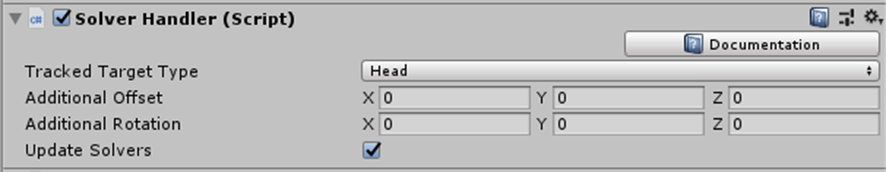
All object with solver behaviour have this component, which sets up basic parameters and toggles the solver effect. For a tracked target type of ‘Head’, it is the gaze cursor (or, more precisely, the gaze raycast) that drives the position and orientation of the object.
The second option, controller ray, uses the raycast from the hand, when it is seen. This, together with the third, hand Joint, only work with HoloLens 2 (as first gen. devices mark only a position in space, without orientation, for the hand position). The last option, Custom Override, allows you to specify the object to track.
Orbital
This solver simplifies locating objects relative to one-another, removing the need for parent-child dependence and the use of local transformations in Unity’s update loops. It is useful where you want to specify relations between objects that can be maintained or changed at predefined rates.
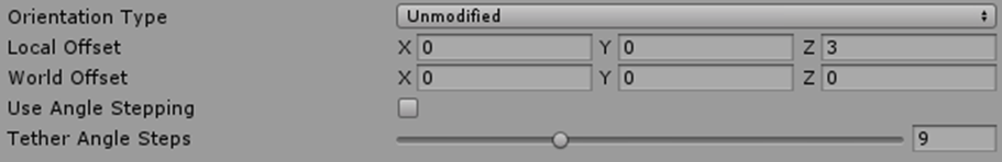
Most options work to move the solver’s gameobject so that the camera always sees the same view of it (I call that ‘bill boarding’), apart from the unmodified orientation type, which will lock the axis of the object as the camera moves around it. Note that with ‘use angle stepping’ turned on, this is no longer the case.
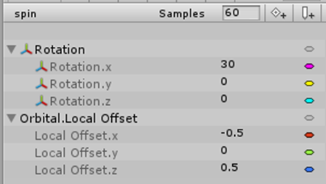
The first example (“satellite”), gives a textured moon that will orbit the player’s hand. It uses the Orbital solver to link the moon prefab to the left hand and then an animator to cycle the solver’s additional offset parameters, giving the object movement. For good measure, there is also a full rotation in Y (around its centre) in the same time frame. I have left the solver’s Orientation Type as ‘Unmodified’.
Radial View
If you worked with the HoloToolkit, you will probably be familiar with its tag-along script. Together with the Orbital solver, the radial view solver performs the same functions while being a far more extensible version of it, in that it can work relative to any of the solver handler’s tracked target types.
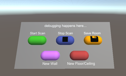
Where you want to control the portion of an object that is inside the user’s viewing area (frustum), the radial view solver is the one for you. This is particularly useful for some types of menu or body-locked user-interface (UI). The next thing we will do is bring in some interface components - these will be useful later when building and modifying the playspace. The sample UI is shown above. There are five buttons in this prefab and a text box for debugging, which we will link to our code.
In order to preserve the orientation, this is the child of a new gameobject that will also have the solver components. We will add the solver handler (as usual) and then the radial view to the parent object. For this particular UI, the following settings provide a fairly non-intrusive, but easily accessible menu system:
Facing world up is chosen to prevent the menu rolling with the head as, in this case, it may produce a less intuitive movement, and hence impair the interaction.
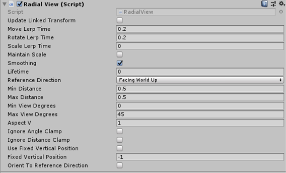
The distance is fixed at 0.5m, to give better predictability of where the menu will be relative to the body and its position is 1m below, to keep it out of the way - it should be there when the user looks down.
Keep in mind that all of these setting depend on the app context as well as stylings and other setting in the prefab - there is no hard and fast rule for working with these, but the guidelines mentioned here will hopefully help to make your menus more useful and intuitive. We will come back to this UI later, but first we will cover the other solver types.
Surface Magnetism
For the next demonstration, I’ve added a Quad gameobject, named it ‘painting’ and attached an image (sprite) to it. On to this gameobject I have added two solver components - Solver Handler and Surface Magnetism.
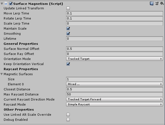
The parameters are quite self-explanatory. The lerp (linear interpolation) and slerp (spherical interpolation) control the smoothing of the movement of object, and will depend on its use (e.g. a menu, projectile or ambient effect). The first 7 properties are common to all solver components.
The surface normal offset is useful when considering spatial understanding (SU), as the SU surface tends to sit slightly inside the spatial mapping surface, in order to give it a smoother, less complex geometry. Raycast ranges should be considered when dealing with larger playspaces (the finished SU surface) or those that have holes (more on this later).
InBetween and Momentum - Building a Catapult
The InBetween solver maintains a position between a gameobject’s position and a second reference point. As with other solvers, this can relate to the head, hand, hand joint or another custom position. Momentum works to give an extra force during smoothing, causing the gameobject to behave as though it has certain physical properties.
To demonstrate these solvers, we will attempt to make a catapult system depending as much as possible on the solver components. Coding is required in two areas - the first to get around a limitation of the solver base script and the second to add catapult reloading behaviour, which could possibly be done entirely in Unity, but is more extensible this way.
First, let’s think about the information flow that can accomplish this:
- Make a catapult and ball objects with simple objects, defining the elastic contact points.
- Define the centre “release” point, in between the contact points.
- Define a hold “pull-back” point, linked to the hand controller ray.
- Give the ball momentum and physics.
- Attach the catapult to the left hand, fire with the right.
- Add interaction events to control pull-back and release.
- Turn off the solver and turn on physics to let it fly.
Object Modeling
The first step is straight-forward, assuming you are happy with the Unity interface. Make three capsules, thin them and orient them so that they form a Y shape. It is recommended you put these under a parent object to help overall moving and scaling. In additional to the visible elements, also add invisible pivot points that act as reference locations at the top ends of the arms of the catapult.
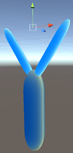
Create another empty gameobject at the same level as the catapult parts that will be the centre point; the target for the initial trajectory of the projectile. Add both a solver handler and an ‘InBetween’ component to this object. Note that, for a static object this won’t change, but we expect a catapult to be a movable object, so it’s wise to have this as a calculated (dependent) position (see image).
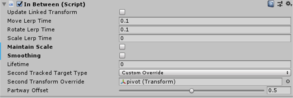
The solver handler will use the ‘custom override’ target type, referencing one of the two pivot points. The other is specified in the InBetween component and the PartwayOffset - the proportion of the distance from one point to the other is set to 0.5, since this will be in the middle. Scale is not important for and we have no need for smoothing at this point, so both these options can be turned off. The lifetime is also disabled as we want this to be persistent, since this point acts as a fixed node for another solver.
The remaining behaviours relate to the projectile, so we will create a sphere as a child of the centre reference point (as, at least to begin with, the sphere’s position will be dependent on it).
On to this sphere, add the necessary solver component: handler, inbetween and momentum.
This time, the handler’s target type is the controller ray, and the inbetween solver use this and the node we just created.
We want to be able to adjust scale and smoothing, so keep these checked.
We will use a value of 0.8 for the PartwayOffset, which means that, when the hand is visible, the sphere will be 80% of the distance to it, from the centre release point.
(Use shift to bring up the hand in Unity).
Physics: Gravity and Momentum
You now have the pull-back position for the sphere. Let’s add physics and behaviours to the ball. The object needs a Rigidbody component with gravity and kinematics turned off. You can also freeze the rotation, which may be useful if the object you are launching is not a sphere.
The Momentum solver has all the normal smoothing parameters as well as some that control the resistance, acceleration and springiness. I have experimented with these and arrived at the shown The Momentum solver has all the normal smoothing parameters as well as some that control the resistance, acceleration and springiness. I have experimented with these and arrived at the shown values though you might find other combinations that produce good results.
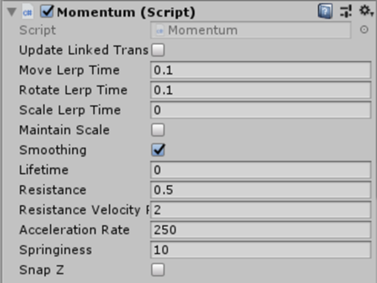
The resistances are kept low, as we do not wish to over-damp the trajectory of the ball in flight, though it is helpful to have these parameters available to the Rigidbody’s.
A high acceleration rate simulates the quick acceleration of the ball on release and values much below lead to a pretty short range. The springiness relates to the spring force acting against the momentum of the object (a form of smoothing) - 10 is a somewhat arbitrary value here.
Interaction
We will first bind the catapult to the left hand (reverse these for lefties) by adding an orbital solver (and handler) to the main catapult gameobject. Keep the additional offset zero and orient the frame (child object) so that it is more typical of how it is held. For me, that’s a rotation of about (10, 0, -20). For the projectile, we bind the solver handler to the right hand and notice that the InBetween component refers to the release position, which will need to be set on reload (more on this later).
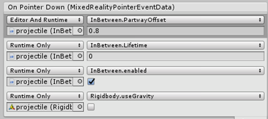
In order to throw the ball forwards, we will change (with interaction) the part-way offset from a point near the hand to the centre release point. We will then allow the interpolation and momentum value to control the movement, for a period of time, before removing the solver’s influence and turning on gravity. These can be done using the PointerHandler script component, which takes mouse pointer (or another controller’s) input events and wraps them in UnityEvents. The interaction I have chosen is mouse click (OnPointerDown) and hold to retract the ball and releasing the mouse button (OnPointerUp) to let it fly.
The final settings for the Pointer Handler’s OnPointerDown event are shown. The first entry sets the profectile InBetween > Partway Offset to 0.8 (from starting value of 0). The second keeps the solver alive. The third ensures the solver is enabled and the last ensures gravity is not affecting it.
It is at this point you will notice that, while the lifetime variable is not available to the UnityEvent. The reason for this is that, while the script does contain a serializable field, allowing it to be displayed in the inspector, there is no public variable (‘set’ method) for controlling it externally. Additionally, forcing a change to this value at runtime (and allowing the solver to disable itself prevents it from being turned back on. This can be fixed, however, with a small addition to the code in the Solver.cs script. After the declaration of currentLifetime, in line 92, I added the following:
public float Lifetime
{
    get => lifetime;
    set => StartCoroutine(SetLifetime(value));
}

private IEnumerator SetLifetime(float _lifetime)
{
    yield return new WaitForSeconds(_lifetime / 2);
    currentLifetime = _lifetime / 2;
    lifetime = _lifetime;
}
This starts a parallel thread which waits for the specified duration and then sets the lifetime of the solver. We then wait half the duration, mark this as the current lifetime and update the variable ‘lifetime’ which is used each frame.
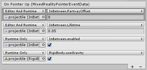
We can now finish the pointer behaviour component. For the OnPointerUp event, we return the PartwayOffset value to zero, beginning the movement to the release point. We then give the solver a lifetime of 0.05 seconds, make sure the solver is enabled and gravity is active, since we now want the behaviour to include physics.
Adding Reload Behaviour
We want to be able to reload the catapult, as a single shot is not much of an application. For this we will put together a ‘CatapultBehaviour’ class, with functions that, when needed, create new projectiles and load them onto the catapult.
Instantiating a prefabricated projectile is the first step, after which we must reconnect it to object in the scene. This means setting gameobject, Rigidbody, SolverHandler and InBetween parameters in a similar pattern to how we updated the PointerHandler in Unity, checking that, on initialisation:
- gravity is off
- the solver handler is linked to the release point
- lifetime is zero (stays alive)
- PartwayOffset places it on the catapult
- the solver is enabled and
- the InBetween component references the release point
We will keep track of the current projectile, since we only want one at a time, and how long it has been alive (‘projectileBirthTick’). Since we do not want to clutter the scene will spent projectiles, I have given each a 5 second lifetime, after which the reload function will destroy the current projectile and make a new one. The trigger for reloading is a click interaction with the frame of the catapult. After setting the public variables in Unity, this script should produce the desired behaviour:
public GameObject ReleasePoint;
    public float ProjectileLifetime;

    private GameObject currentProjectile;
    private long projectileBirthTick = 0;
    private long lifeTimeInTicks = 0;

    void Start()
    {
        lifeTimeInTicks = ((int)(ProjectileLifetime * 100)) * 100000;

        currentProjectile = GameObject.FindGameObjectWithTag("Respawn");
        if (currentProjectile != null)
        {
            projectileBirthTick = DateTime.UtcNow.Ticks;
        }
        ReloadCatapult();
    }


    private void CreateProjectile()
    {
        currentProjectile = Instantiate(Resources.Load("Prefabs/projectile") as GameObject, ReleasePoint.transform);
        currentProjectile.GetComponent<Rigidbody>().useGravity = false;
        projectileBirthTick = DateTime.UtcNow.Ticks;

        SolverHandler mySH = currentProjectile.AddComponent<SolverHandler>();
        mySH.TrackedTargetType = Microsoft.MixedReality.Toolkit.Utilities.TrackedObjectType.CustomOverride;
        mySH.TransformOverride = ReleasePoint.transform;

        currentProjectile.GetComponent<InBetween>().Lifetime = 0;
        currentProjectile.GetComponent<InBetween>().PartwayOffset = 0;
        currentProjectile.GetComponent<InBetween>().enabled = true;
        currentProjectile.GetComponent<InBetween>().SecondTransformOverride = ReleasePoint.transform;
    }


    public void ReloadCatapult()
    {
        if (currentProjectile == null)
        {
            CreateProjectile();

        }
        else if (DateTime.UtcNow.Ticks - projectileBirthTick > lifeTimeInTicks)
        {
            Destroy(currentProjectile);
            currentProjectile = null;
            CreateProjectile();
        }

    }
}
Controls for Running it in Unity and on the Emulator
So far everything should look good when running the Unity scene to test. The editor controls are as follows:
- Left shift > left hand visible (double tap the key to keep it permanently on)
- Left click when left hand visible performs air tap.
- Space > right hand visible (again, with double tap option)
- CTRL+ left click air taps on this side
- Right click and hold turns the camera
- WASD and arrow keys move you about,
- Page up and page down control elevation
- The Alt key will change which hand interacts with a left mouse click.
If you are happy that it works in principle, let’s go to the emulator to finish the check and identify any bugs or unwanted behaviours. The controls for the emulator are found here.
Testing the Catapult
In terms of catapult mechanics, the lifetime value’s effect is dependent on the initial speed. When too large it causes the ball to get stuck at the release point or, if too small, does not allow the projectile to build up enough speed to have any range. Since successful timing is also a function of the pull-back distance of the projectile, it would be more sensible to calculate this on the fly.
The other glitch worth noting is the oscillation of the projectile at the pull-back point. This is the results of competing solvers and, while it could be helped with smoothing values < 0.1, this should be accompanied with changes to the acceleration, resistance and lifetime variables. There are several possible combinations, though all rely on a momentum-release timing combination. I am sure that, with some experimentation, a smooth but effective set of parameters can be found.
 Final Words
You should now have a few working examples of solvers. Unity developers are increasingly moving to more modular design and the scene/prefab structure is used here to help port these examples into your project without too much work. I have avoid searching for gameobjects and used only a tag which is also defined in the prefab, though this could be separated further.
If you have any questions or would like more guidance on anything found here, feel free to drop me a line at: william.guest@open.ac.uk
Thanks for spending the time to learn about MRTK and solvers! I hope this helps you to build the next generation of immersive experiences.