 3D Modeling & Rendering
Content
Introduction
There are several techniques of creating a virtual representation of 3D models. The surface of an object can be approximated by a graph structure which is called mesh. An advantage of meshes is that the creator can decide how complex the geometry of an object may become. Based on this, the performance of the final application can be optimized by reducing the mesh complexity on unimportant objects. However, a disadvantage is that it is not possible to create perfectly rounded surfaces. The smoother a curvature should be, the more refined the mesh needs to be. This will affect the application’s performance. Alternatively, 3D models can be created using Computer-Aided Design (CAD). The strength of CAD is that is works with exact mathematical definitions of shapes. This leads to perfectly curved surfaces which are for instance required when designing a car. Both meshes and CAD focus on the outside hull of an object and disregard its interior. This is addressed in the volumetric representation of objects. It stores density values in a three-dimensional grid which provides information about the shape of the object as well as its inside. Volumetric representations are often used in medicine in order to get a meaningful visualization a patient’s body.
Modeling Techniques
Mesh-based 3D models can be created using a number of techniques. It is also possible to combine these techniques in one workflow.
Compositing Primitives
A beginner-friendly way of manual modelling is to approximate objects by a composition of primitive shapes like cubes or spheres. Such basic shapes are usually included in 3D programs by default and can directly be added to a scene. The primitives are moved, rotated, scaled and stretched in order so that they fit the target object as good as possible. For instance, a table can be approximated by creating five cubes. One of them is compressed along the vertical axis and represents the tabletop. The other four cubes are stretched into thin and long cuboids and are aligned with the corners of the tabletop. They act as the legs of the table.
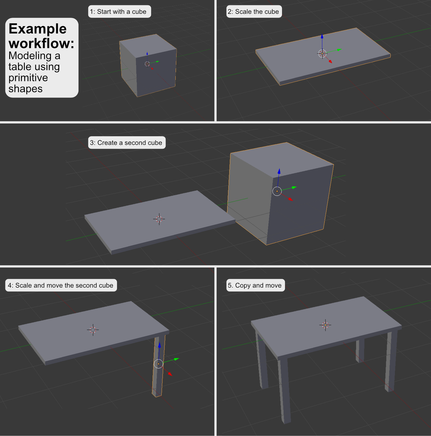
This technique only requires transformations, rotations and scaling operations and therefore, objects can be created without much effort. Thus, results can be achieved quickly. However, the basic shapes can only approximate the object. Intricate shapes and especially organic forms cannot be modelled with this technique. Primitives are best used to prototype a scene (missing reference), e.g. to block out the general shapes of objects and to establish its proportions. Additionally, primitives can also be used as a starting point, e.g. for subsequent manual modelling or sculpting processes.
Boolean Operations
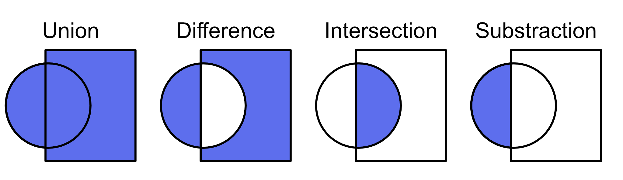
One can also use Boolean operations in order to create complex 3D shapes from multiple base meshes. Boolean operations are heavily used in CAD where they are defined on volumes. The volumes are combined using operations known from Boolean algebra, e.g. OR, AND or XOR.
Intuitively, the for every point in space and every base volume, a truth value is determined (Foley, 2010). It states if the point is part of the volume. By combining the truth values for this point using a Boolean operator, one can determine if the point is part of the resulting volume. For instance, the union operation combines the points of the base volumes using the OR-operator. Therefore, a point is part of the resulting volume if it is part of any of the starting volumes. For the AND-operator, a point is only part of the resulting volume if it is part of all base volumes. This corresponds to the intersection of the objects. The subtraction operation can be achieved by the NOT operator. Here, the result volume consists of all points which are part of the first volume but are not inside the other volumes. The subtraction is not symmetric, i.e. it yields different results with different volume orders.
Boolean operations also work on meshes. Here, the volume is regarded which are encapsulated by a mesh. The expected result is a mesh which encapsulates the resulting volume. To achieve this, special algorithms are used to clip the individual meshes, e.g. the Greiner-Hormann clipping algorithm (Greiner & Hormann, 1998) or the Vatti clipping algorithm (Vatti, 1992). The trimmed meshes are combined into one resulting mesh.
Digital Sculpting
Digital sculpting is inspired by real clay sculpting. Similar to real sculpting, the 3D artist starts with a base shape and can pull and dent the virtual material to create bumps and creases. Usually, the large shapes are defined first and then progress is made on smaller details. These operations are performed in a 3D sculpting program using a mouse or a tracked stylus (Simonds, 2013). A difference to real sculpting is that it is possible to dynamically add or remove volume at any point which enables the sculptor to extend the object in any way. During the process, the sculpted mass is automatically defined by a mesh which is managed and optimized by the sculpting program.
With digital sculpting the 3D artist can focus on forming the shape of the object without worrying about the underlying mesh geometry. Like manual modelling, it is possible to create real and imaginative objects. However, just like real sculpting, training is required in order to achieve results with high quality. Digital sculpting is well suited for creating organic shapes, e.g. for designing characters. Sometimes, it is also used in a creative way to prototype the shapes of an object with hard edges.
3D Scanning
Another option for creating digital 3D models is 3D scanning. In this process, a real object is measured using a 3D scanner. Usually, these scanners work with a light-based method to extract height data and compose them into the 3D shape. The result is a point cloud. In software programs such as Meshlab, the point cloud can be converted to a mesh. The mesh usually needs post-processing, e.g. in the form of remeshing to create a version with managable topology and polygon count which can be used in a real-time engine.
The tutorial chapter 3D Scanning and Animation provides an example workflow for creating a 3D model with a structure sensor for the iPad.
Photogrammetry
It is also possible to use structure-from-motion photogrammetry to create 3D models (Westoby et al., 2012). Photogrammetry is also a 3D scanning technique but it only requires a standard camera. With this camera, a series of photos is taken from various different angles and positions. Alternatively, it is also common to use an array of cameras which are all triggered at the same time to take a photo. The photos are later processed in photogrammetry software in order to generate the 3D model. The software looks for common feature points in the images and tries to match them. Because of the fact that the images have been taken at different positions, the feature point is shifted in the other image and so the software can determine the depth of the feature point. This is similar to the way how humans can perceive depth from parallax motion, e.g. when looking out of the window of a moving train. Objects which are close to the viewer like signal installations at the rails will quickly move through the field of view while distant trees seem to travel through the field of view at a slower speed.
Photogrammetry is capable of producing realistic results since it does not only provide geometry information but can also project the original images onto the 3D model in order to create a texture. Among other areas of application it is used in aerial photography and archaeology.
3D models from photogrammetry can be created with the commercial software products Agisoft Metashape, RealityCapture, Autodesk ReCap and the open-source tool Meshroom.
Manual Mesh Creation
The previous methods all work on an object-level where the modeller is only concerned with the shape of the object while the computer constructs the according mesh data. However, it is also possible to manually construct the mesh. This means that the 3D artist adds and manipulates individual vertices and defines edges and faces in order to build the final mesh. One can either start from scratch or adapt existing primitive shapes. An example would be the (artistic) modelling process of a car. (In the production process, cars are usually modelled with CAD shapes since they can define exact and smooth curvatures. However, for real-time applications like games, cars are modelled as mesh-based objects). In this example, a 3D artist could start with reference images of the real car which are placed on the top view, front view and side view. After that, vertices are placed one by one in such a way that they align with all three background images. When placing the vertices, they are connected to edges and also form faces. Here, the 3D artist needs to make sure that the edges and face strips follow the major forms of the car’s body. Additionally, the topology of the mesh needs to be managed, e.g. to avoid a mesh that is too dense. 3D programs offer different features to support the modelling process. Especially a series of generative modifiers like live-mirroring for symmetric shapes or automatically subdividing edges to add more vertices accelerate the process and improve the result (missing reference). Creating realistic 3D objects using this technique requires training and in-depth knowledge of the supporting features. A wide range of tutorials exist online which teach how to create different objects and explain different tricks which can be used to maximize the effectiveness of the modelling program’s features.
With mesh creation, the creator has full control over the mesh’s complexity and topology. This is helpful for optimizations, e.g. if the model should be used in real-time rendering. Additionally, a clean topology helps in managing the amount of detail which is portrayed in the mesh. It is also helpful for animatable objects since the topology can be laid out in a way that it supports the movements. The main disadvantage of this technique is that it is a tedious and slow process. Similar to drawing, the quality of the result depends on the artistic skills of the creator. Apart from defining the shape of the object, the modeller also has to think about a suitable topology to represent the shape as a mesh. The technique works well for man-made objects since they consist of clear shapes and hard edges which are good reference points in the modelling process. Creating organic objects by hand this way is tricky.
Box Modeling
Box modelling describes a method in which faces of a polygon cube are extruded and manipulated to create a complex model. The process generally utilizes a simple iterative method where extruded faces are moved, scaled and rotated to represent an object. The name box modelling refers to the use of a cube as a starting point and often has a very angular result. Final stages of the project may work with smoothing functions to provide a more organic look, however during development it is optimal to retain a low polygon count.
Retopology
The presented modelling techniques of digital sculpting, 3D scanning and photogrammetry typically result in a high-density triangle mesh. The problem with this mesh is that it is irregular and often bears unnecessary complexity (missing reference). For instance, a 3D scanned table consists of many small triangles but its table-top could be simplified to one cuboid shape which only consists of two triangles per side. Additionally, it is not possible to animate the high-complexity 3D meshes since any movement results in condensed geometry and stretched surfaces. In real-time rendering, the amount of polygons also has an impact on the runtime of the rendering pipeline. This means that high-density meshes will take longer to render and therefore the framerate will be lower. Due to this, complex meshes should be retopologised (Pan et al., 2018). In this technique, the high-density mesh resulting from the sculpting process or 3D scan is used as a base mesh. After that, a new mesh is created on top of this base mesh. This can be done manually or by an algorithm. The new mesh is typically created using quads and it considers the shape of the object and how it might be animated. As a main idea, the quads form strips which should follow the object’s main curves and which should align to any hard edges (missing reference). Since the manual creation of such a retopology mesh is tedious and time-consuming, there are algorithms which automate this process (Pan et al., 2018). The result of the retopology is a mesh which describes almost the same shape as the original high-density mesh but it is more lightweight and optimized. However, the retopology process may lose some details which were captured by the high vertex-density of the original mesh. To solve this, the difference between the two meshes can be “baked” into a displacement or normal texture. This way, small details can be captured in the texture and are shown by the shader. Details on this displacement and normal maps are described in the “Textures” section.
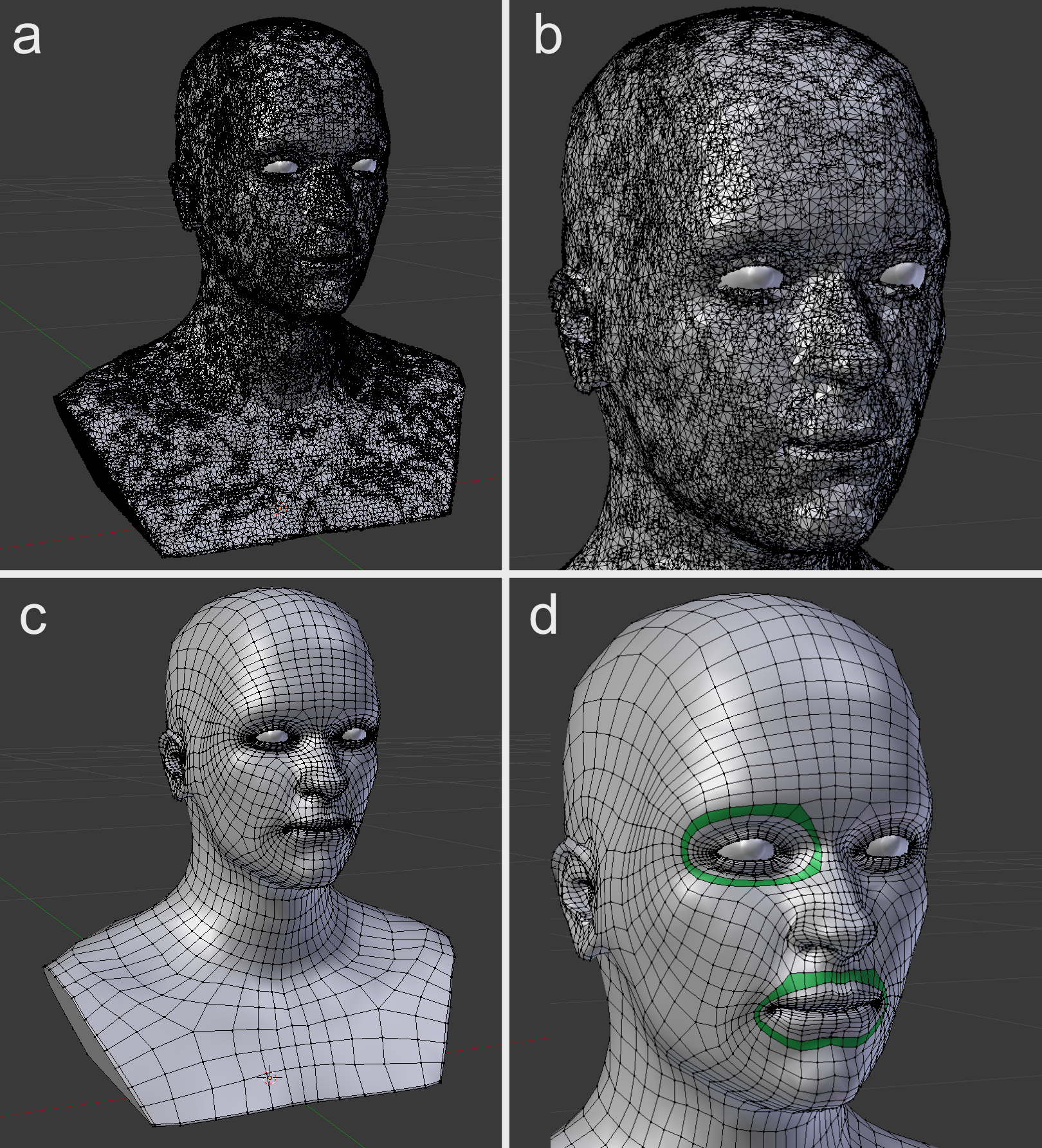
b: Cutout of (a) showing the geometry.
c: Manually retopologised mesh using quads.
d: Cutout of (c) showing the geometry. A selection of important face loops is highlighted in green.
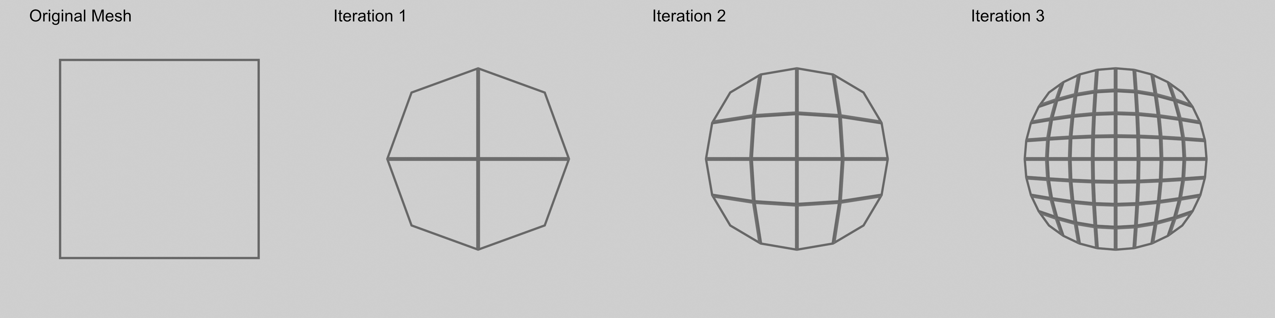
Subdivision Surface Modeling
A technique which is used for creating smooth, organic surfaces is called Subdivision Surface Modeling (DeRose et al., 1998). The modeller constructs a guide mesh. After that, an algorithm constructs a smooth version of the modelled shape. It achieves this by subdividing the faces of the guide mesh and by calculating the vertex positions of the resulting mesh with regard to the vertex positions of the guide mesh. There are different algorithms which differ concerning the position calculation rules. Once the algorithm has been applied, the resulting mesh can act as a new guide mesh for the next iteration of the algorithm. Thus, the geometry can be smoothed further by applying the subdivision surface algorithm recursively. However, this also yields a mesh with more vertices (Catmull & Clark, 1978).