 Texturing 3D Models
Contents
Textures
Textures are images which are applied to the 3D object’s faces, e.g. to give colour to the surface. More details about textures are described in the chapter about Computer Graphics.
UV-Unwrapping
Since image textures are two-dimensional data, a mapping is needed from the 3D room with the object to the 2D space with the texture. It defines which texture pixel, also called “texel”, is displayed on the mesh’s face. The process of creating this mapping is called UV-unwrapping. Intuitively, the mesh is cut open at some edges so that its 3D shape can be unfolded into a flat form. The image texture is applied to this flat representation.
More technical, each vertex of the mesh is mapped to a 2D vertex in the space of the texture and with new connectivity data. The 2D texture space is also called UV-space, the two axes are labelled with U and V instead of X and Y. This distinguishes the UV-coordinates which are associated with a texture with points in the 3D room. UV-coordinates range from 0 to 1 with the point (0,0) at the left bottom of the image and (1,1) at the top right. This also means that UV-points are independent of the texture resolution and are scaled with the image. When UV-unwrapping an object, its faces are laid out on the texture. Good UV-unwrappings minimise the amount of stretching. Stretching occurs if the shape of a face is distorted in the UV-space. Especially curved surfaces like a sphere are difficult to UV-unwrapping without stretched textures.
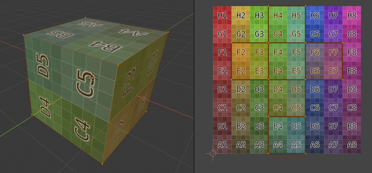
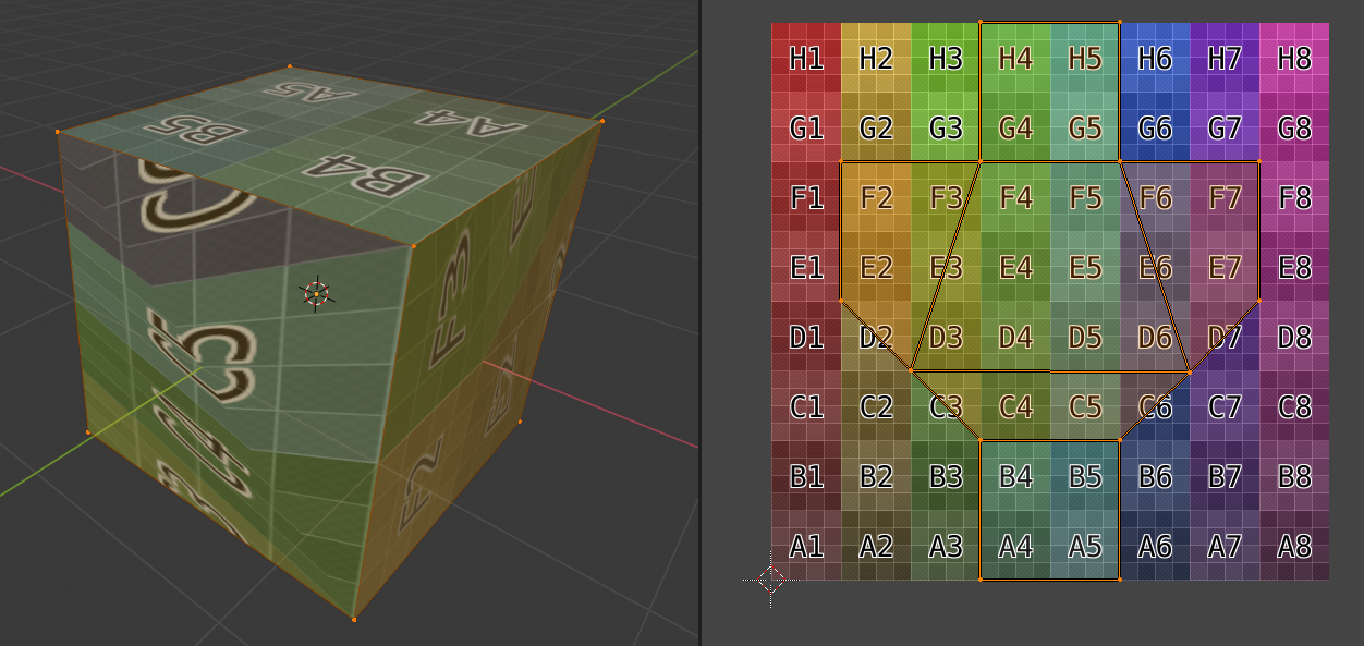
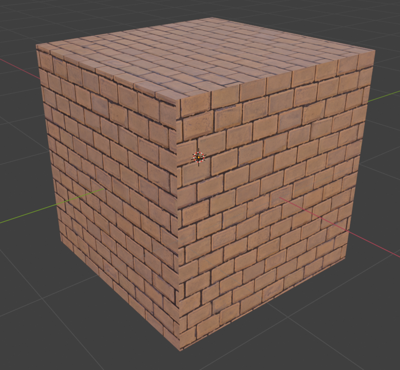
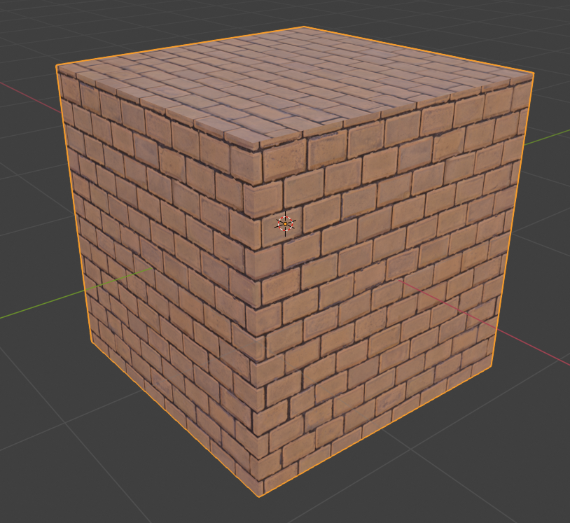
To minimize the stretched textures, edges of the mesh can be marked as seams. This means that the faces which are not connected in the texture space. Subsequently, a vertex in the 3D space can be mapped to multiple vertices in the UV-space if the adjacent edges are seams. The problem of seams is that they create discontinuities in the texture on the faces. For instance, if a brick wall texture is applied to a cube, it can happen that the “lines” of brickwork do not match up at the seams. Hence, a 3D artist has to do manual corrections by moving the unwrapped face on the texture until the seams match. For this reason, seams are often placed in areas which are less visible to the virtual camera.
Texture Resources
There are various online repositories which offer photo textures for varying purposes and with different qualities, prices and licences. A large amount of these online resources offers PBR-compatible textures which means that it does not only provide image textures but also other data like normal maps, metallic maps, roughness/smoothness maps and ambient occlusion maps.
Here is a list of such texture repositories:
| Name | Web address | Price | License | PBR | Number of textures |
|---|---|---|---|---|---|
| CC0 Textures | https://cc0textures.com/ | Free | CC0 | yes | > 700 |
| Poliigon | https://www.poliigon.com/ | Annual or monthly subscription ($12 - $47 per month) | Based on the subscription plan | yes | > 3100 |
| Texture Haven | https://texturehaven.com/textures/ | Free | CC0 | yes | > 140 |
| textures.com | https://www.textures.com/ | Per texture (low resolutions are free; requires registration) | Per texture | mostly | > 7500 |
Apart from downloading online resources, it is also possible to create textures from photos, procedural logic, photoscans and by hand-painting them.
Texture Painting
Textures can be created in photo editing and drawing applications such as Adobe Photoshop or GIMP. However, it is difficult to paint details on the texture which should appear at a certain position on the model because the UV-layout needs to be considered. Therefore, 3D programs provide a texture painting mode which allows the user to directly paint on the 3D model. Pen strokes are transferred onto the underlying image texture with respect to the UV-layout. Apart from manually painting the colour, one can also use a clone tool to blend different photorealistic textures into each other. This way, small details can be set up quickly and obvious tiling patterns can be hidden. For instance, a mud material can be set up separately of a water material. After that, the two materials can be blended together by hand-painting a mask which defines puddles on a muddy ground.
Another technique is projection painting. A 2D texture is shown as a semi-transparent overlay on the screen. Behind the texture, the 3D object can be seen. When painting, the texture is projected onto the 3D object based on the current viewpoint.
The following table contains a list of tools which can be used for texture painting:
| Name | Web address | Price |
|---|---|---|
| 3D Coat | https://3dcoat.com/ | $99 - $568 |
| Armorpaint | https://armorpaint.org/ | 16 Euro, optional subscription to support developers (Open-Source) |
| Blender | https://www.blender.org/ | Free (Open-Source) |
| Substance Painter | https://www.substance3d.com/products/substance-painter/ | Monthly Subscription ($19.90 - $99.90) |
 Exercise: Texture Painting in Blender
The goal of this exercise is to create a die. To achieve this, you will texture paint the sides of a cube so that they show the according number of eyes.
1.Blender’s startup scene already contains a cube which will act as the mesh for the die.
If you already deleted the cube or changed the startup file, you can create a new cube by pressing Shift + A and selecting Mesh > Cube.
In Blender 2.8, the primitive mesh types are already UV-unwrapped.
Hence, we do not need to worry about UV-unwrapping.
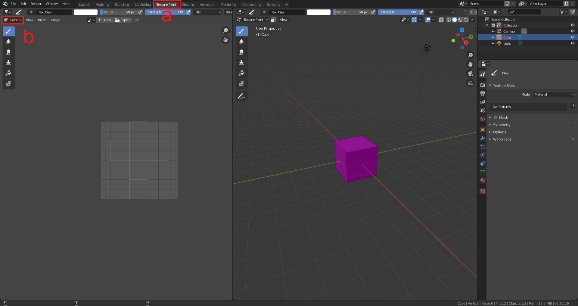
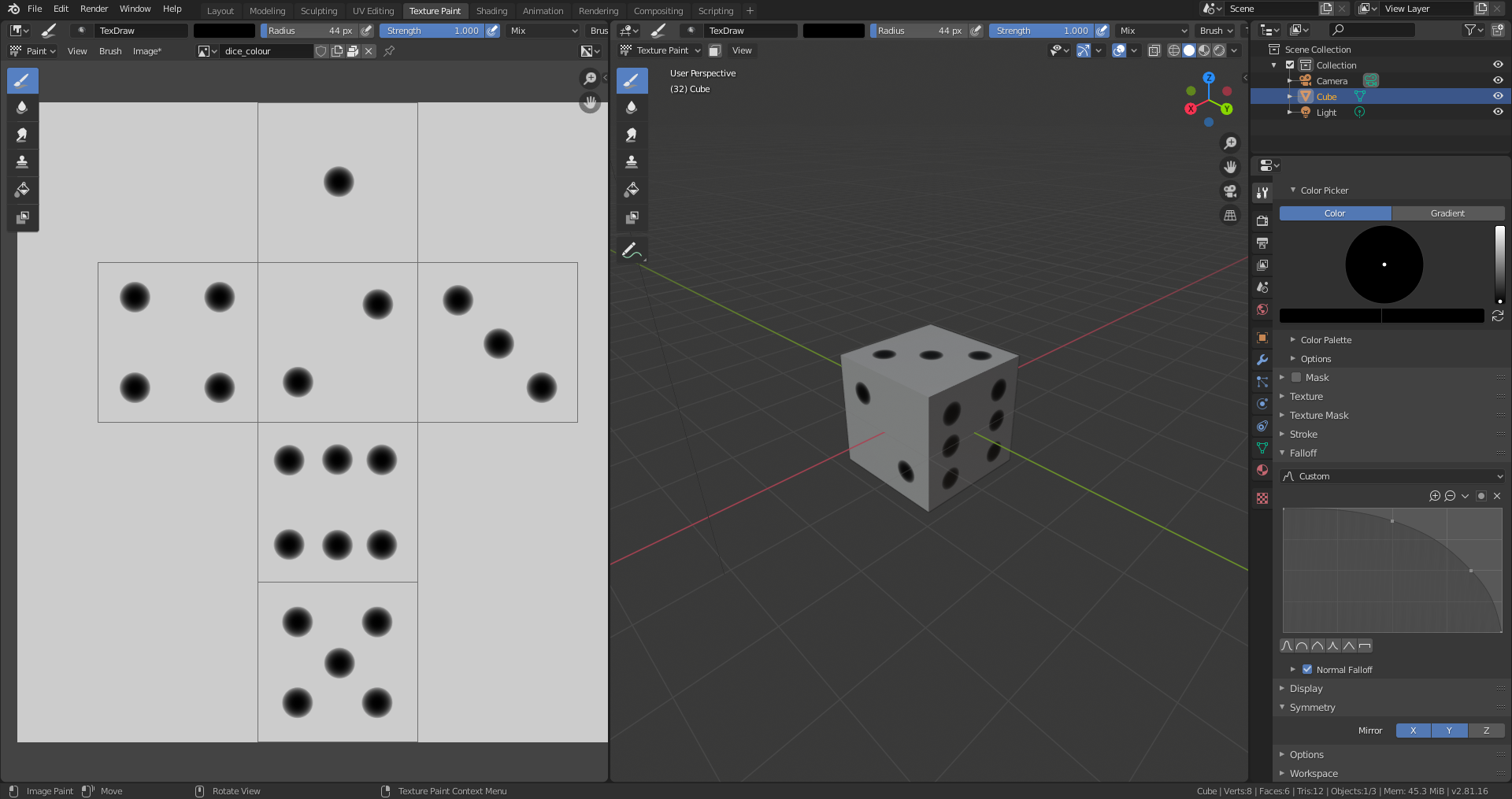
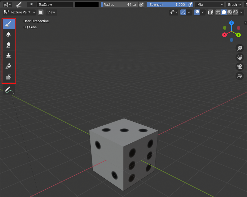
2.At the top of the window, a series of tabs can be found.
They act as pre-defined workspace configurations for common tasks in the 3D modelling programme.
Select the tab which says “Texture Paint”.
In the figure it is highlighted by a.
The workspace changes to a two-split view.
On the left side, an image editor can be found.
On the right side, the 3D view is situated.
Switching the tab did not only alter the alignment of the panels in Blender.
It also switched from Object Mode, where users can examine 3D models without editing them, to Paint Mode.
This can be seen in highlight b of the figure.
In paint mode, we can draw on the 3D model.
However, at the moment this is not possible.
You might have noticed that the cube turned purple.
A solid purple colour is an indication for a shader error.
In this case, we are missing a texture.
Since we can only paint on textures, we need to add one to the cube.
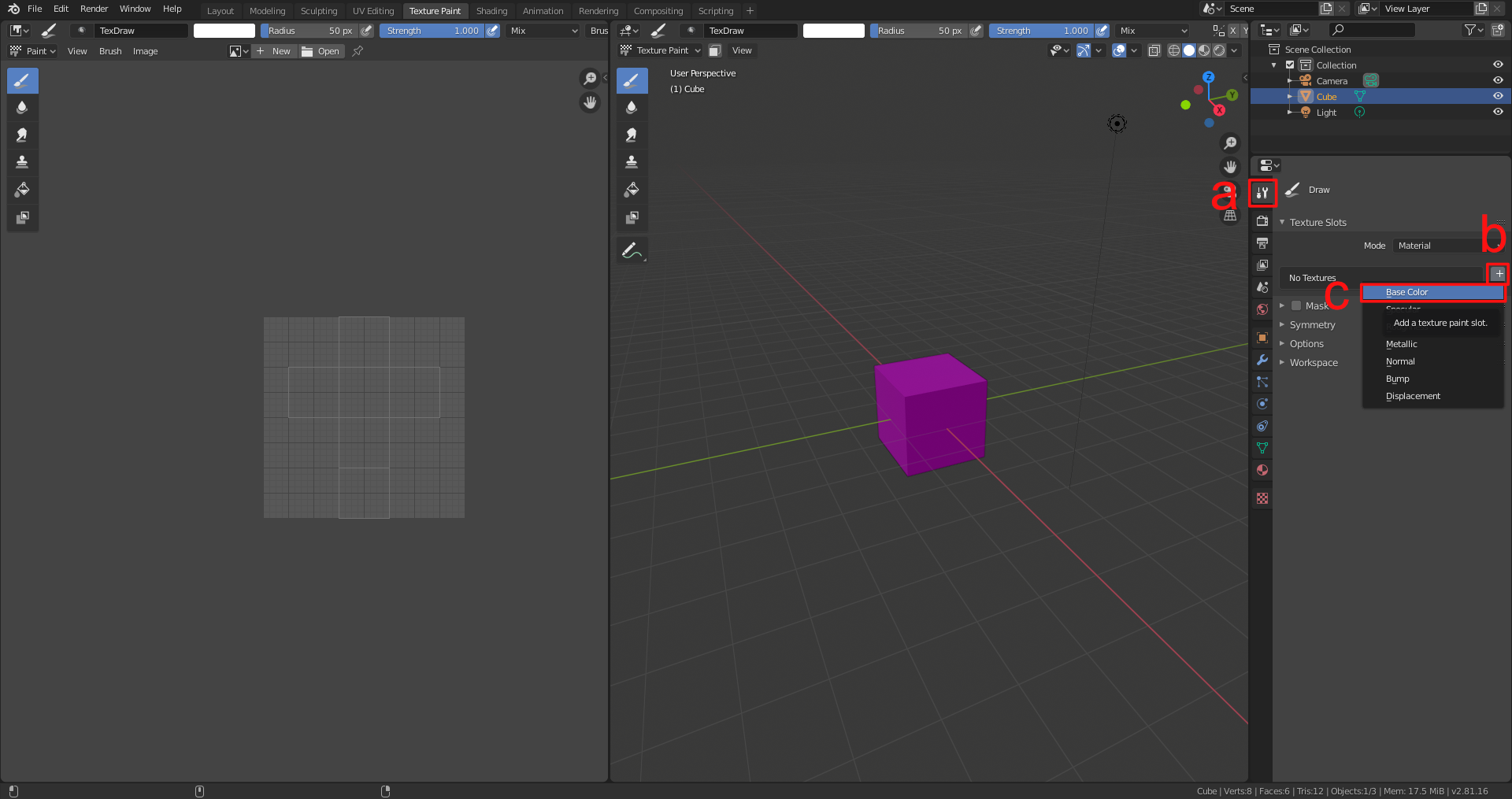
3.We will now add a texture to the cube.
- The controls for this operation are situated on the right in the inspector.
Make sure that the sub-tab with the screwdriver and wrench icon is selected.
It is highlighted as item
ain the following figure. This panel shows options for the current tool and workspace settings. In this case, it provides options for texture painting since this mode is active. In the section texture slots, click on the small plus next to no textures. The button is labelled asbin the figure. - This will open a menu where you can decide which texture slot should be populated with a texture.
Each texture slot has a different purpose.
More information on different texture types can be found in the chapter Computer Graphics.
For now, we want to create a texture that determines the visible surface colour of the object.
Hence, select the option Base Color.
It is marked with
cin the figure.
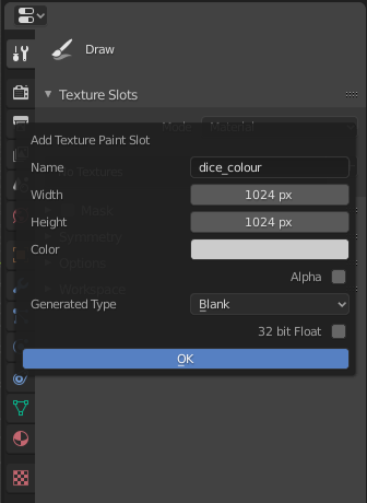
4.Another menu will open up where you can specify a name, width, height and colour. According to these properties the texture will be created. For the name, it is a good idea to assign a meaningful name and also indicate that this is a texture for the colour. You can for instance name the texture dice_colour. Textures should usually be quadratic and have a width and height which is a power of two, e.g. 2, 4, 8, 16, 32, 64, 128, 256, 512, 1024 or 2048 pixels. The bigger the texture, the sharper the texture will look. However, larger textures also use more memory. 1024 pixels are a good standard value. The texture will be initialized with the given colour. You can leave it at the default 80% white. One can also state whether or not the texture should have an alpha channel. In this example, we do not need it since the dice does not have transparent parts. The Generated Type dropdown box should be set to Blank. This will create a texture with a uniform colour. The other options of this dropdown-menu create pre-defined textures for testing purposes which show different kinds of grids. Leave the 32-bit Float checkbox deselected. If it is checked, the texture has a higher bit depth and therefore higher accuracy for the values. But this is not needed here. Finally, hit OK.
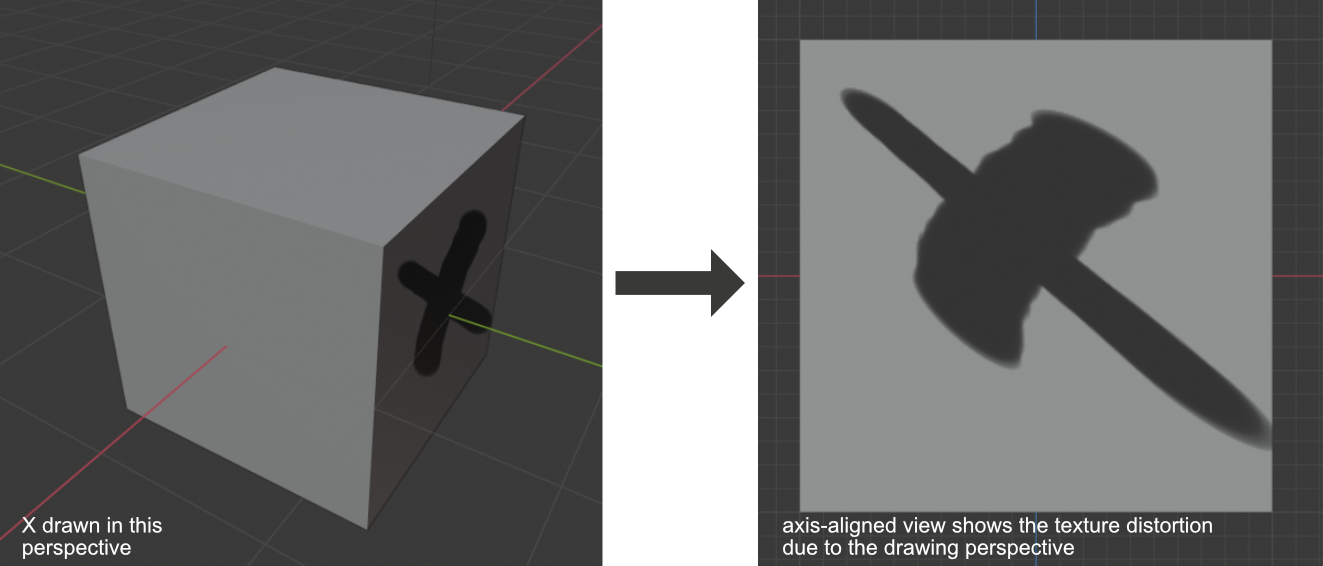
5.The cube should now have the white/grey colour which was set in the texture generation menu. If you hover your mouse over the 3D view, a white circle surrounds the mouse cursor. This circle indicates the size of the brush. If you click and drag on the surface of the cube, you can draw white strokes. Create a one or two test strokes to get a feeling for the mechanic.
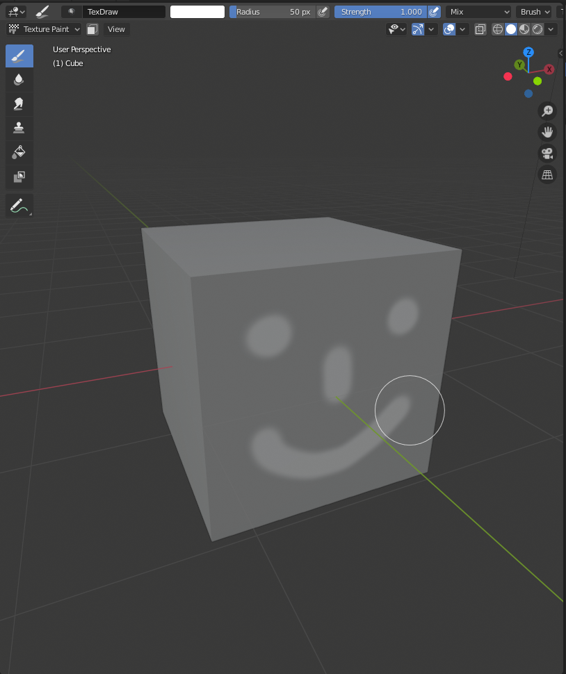
Note that the brush stroke is projected from the current viewing position. Therefore, painting a surface at a very steep viewing angle will distort the stroke.
6.Undo any test strokes you just did with Ctrl + Z.
We would like to add black eyes to the dice.
Thus, we need to change the colour of the brush.
This setting can be altered in the inspector on the right side.
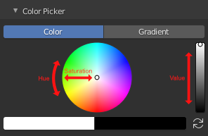
There is a colour wheel in the brush section under Color Picker.
Hue and saturation can be defined on the wheel itself as seen in the figure.
The value of the colour can be set with the slider next to the colour wheel.
Pull the slider down to the black end of the slider.
You can now paint black brush strokes.
7.Align your camera with the front of the dice.
You can do this by hovering over the 3D view with the mouse and pressing NumPad 1.
The brush circle gives a preview of the position and size of a dice eye.
You can change the brush size by shortly pressing F and moving the mouse.
To confirm the new brush size, left click.
8.Draw one test eye by positioning the cursor over the cube’s surface and left click once.
This creates a filled black circle.
However, we now see that the drawn circle does not yet look like the eye of a die.
It has a smooth falloff which means that the corners of the circle are blurred and fuzzy.
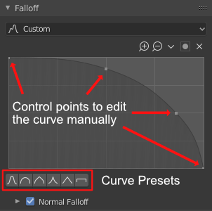
To change this, expand the Falloff section in the inspector.
It contains a graph with a smooth curve.
The curve defines the drawing intensity of the brush stroke at different positions on the brush.
The left side of the graph defines the strength near the middle of the brush’s circle.
On the right side of the graph, the strength at the rim of the brush circle is controlled.
Underneath the graph, there is a series of preset buttons showing some curve shapes.
You can experiment with some of them and see how the drawing pattern changes accordingly.
It is also possible to manipulate the curve in the graph directly by its handling points.
Since we want a circle with a well-defined rim, we can either take preset with the constant value (the last one on the right) or the circular shape (second one on the left).
The constant value gives a sharper rim but it also shows stepping artefacts since no blending is performed.
The circular shape produces a relatively sharp rim but also blends the pixels at the borders to avoid stepping artefacts.
9.Now that the brush is correctly set up, you can paint the eyes of the dice.
You can change between different axis-aligned views with the numpad keys:
- Numpad 1: Front View
- Numpad 3: Right Side View
- Numpad 7: Top View
- Ctrl + 1, 3 or 7 gives the opposing side, i.e. Back View, Left Side View and Bottom View
It is best to avoid zooming in or out while painting and to avoid altering the brush’s scale so that all eyes have the same size.
An alternative way of painting is presented in the section “*Further things to try out”.
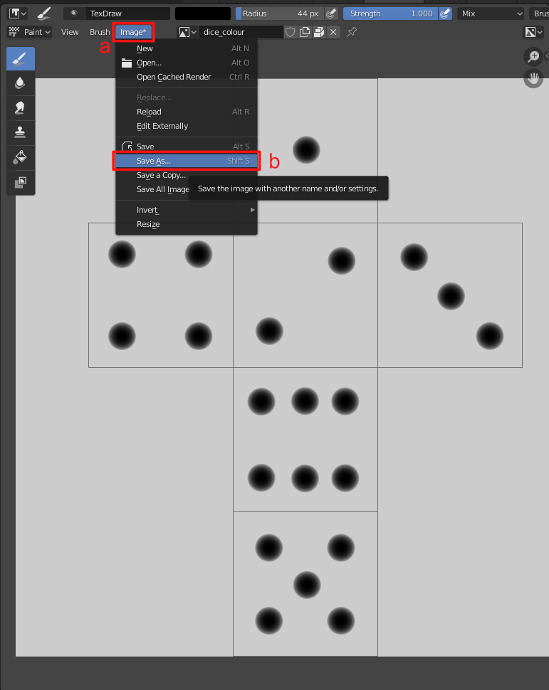
10.It is important to know that the painted texture is not yet saved. By default, it is not included in the .blend-file and so saving the project will now save the texture. Instead, textures need to be saved separately as an image file to persist. This can be done in the Image Editor panel on the left side of the two-split view. First, we need to load the texture that was just created. At the top, there are two buttons New and Open. Click on the small dropdown field next to the New button which shows a triangle, a rectangle and a small circle. This dropdown menu shows all textures which are referenced in the .blend-file. Select the dice_colour texture that you created. The editor will now show the image and an overlay of the UV-unwrapped cube. Next, go to the top menu of the Image Editor and select “Image > Save as…”. Save the image somewhere on your hard drive, ideally in the same folder as the .blend-file.
11.Any changes to the texture need to be saved manually.
If you alter the texture, go to Image > Save or hover the mouse over the Image Editor and hit Alt + S to save the currently displayed texture.
Further things to try out
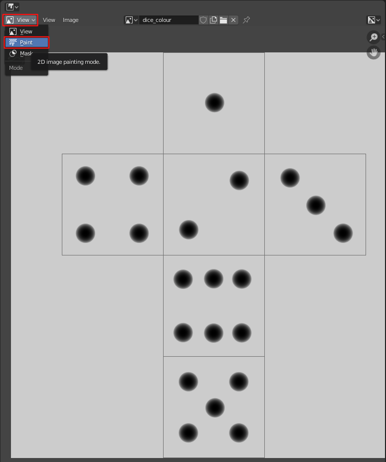
- You can also paint the eyes in the Image Editor. In the top-left corner of the Image Editor, change the dropdown menu which says “View” to “Paint”. You now have the same drawing abilities in the 2D texture view. If you paint either in the texture view or on the 3D model, the other view will update in real time.
- On the left side, there is a menu which shows different brushes.
If the menu is not visible, press
Tto toggle its visibility. The menu contains some brushes known from image editing software, e.g. a smear tool, a clone brush and a fill bucket.
- In the inspector, there is a symmetry section which allows you to automatically mirror brush strokes when painting them.
- You can re-use the colour map as a depth map to carve the eyes out. Alternatively, you can create a second map for the depth and draw surface dents there.
Texture Baking
Textures can also be baked by 3D programs. In this process, information are calculated and stored in a texture. This technique can be used to improve the performance of a real-time application if the lighting situation never changes. The 3D program can pre-calculate the lighting situation once and write the results for each object into textures. After that, the textures are applied to the 3D objects. The scene does not require any light sources any more since all information about shadows and surface brightnesses are already included in the textures on the objects. Since the baking algorithm can use a raytracing renderer, the baked results can be more realistic than the real-time version. Real-time render engines only use approximations of light effects, e.g. to calculate shading and shadows. In comparison to this, raytracing algorithms simulate individual rays of lights with their reflections and refractions to obtain realistic lighting information. For instance, indirect lighting by light which was reflected by other surfaces can be calculated in an accurate manner with a raytracing engine. Another example are caustics which are produced by transparent objects, e.g. lenses which focus light on one point.
Texture baking is also used to create normal maps. In this workflow, a 3D artist creates a high-resolution model, e.g. by sculpting it. After that, it is retopologized to a low-resolution model which is suitable for real-time rendering. In the retopology step, a lot of fine details are lost. They can be recovered by baking the normals of the high-resolution mesh onto the low-resolution mesh.
Exercise: Texture Baking in Blender
Baking Lighting Information
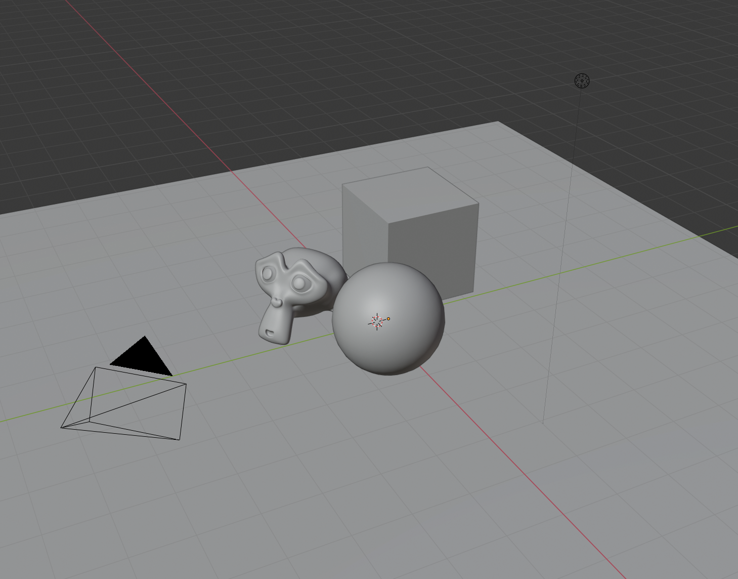
1.Create an interesting scene in Blender with some basic objects.
To add objects to the scene, press Shift + A and add meshes such as a cube, sphere or monkey.
Create a ground by adding a plane.
To arrange objects, press the G key and then move the mouse.
The movement operation can be confirmed by left-clicking and cancelled by right-clicking.
2.Select the sphere and monkey objects by left-clicking on them (you can also select multiple objects by holding down Shift while left-clicking).
After that perform a right-click and select Shade Smooth which gets rid of their facetted look.
With the monkey selected, press Ctrl + 2 to add a subdivision surface modified of level 2 to the monkey.
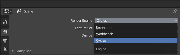
3.Switch the render engine from Eevee to Cycles in the toolbar. Eevee does not produce accurate results since it is optimized for real-time performance with simplifications in the shading process. Cycles is an unbiased raytracing engine which produces physically accurate results with regard to reflections and indirect light bounces.
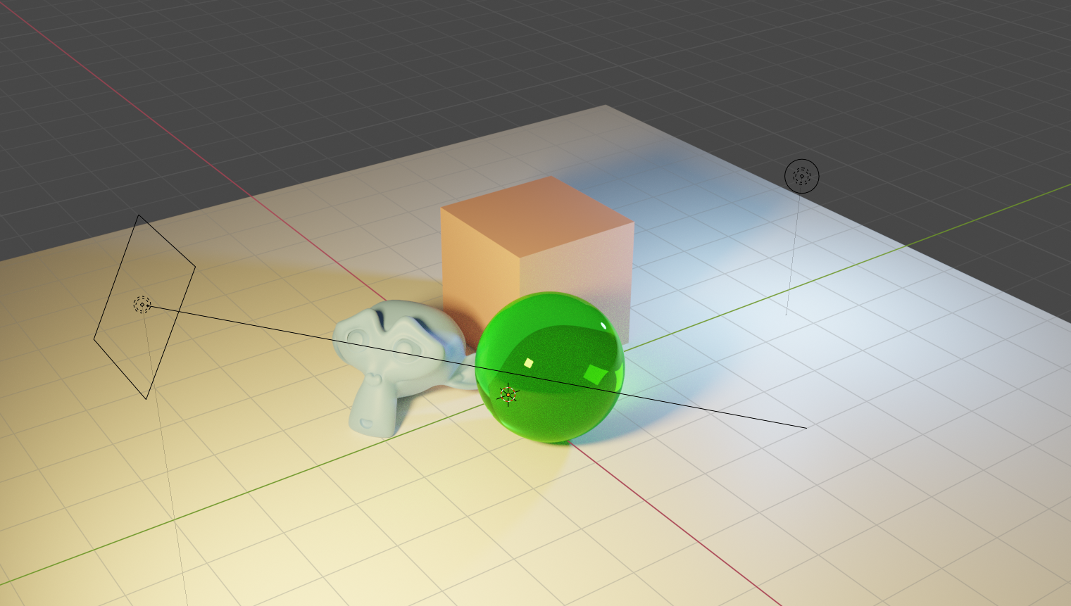
4.The lighting should also be adapted so that we get interesting illuminations and shadows.
Add an area light and place it so that the monkey and sphere cast shadows onto the cube object.
You can also place a point lamp on the opposite side of the objects.
An interesting effect can be achieved by tinting the colour of the lights so that they are not completely white any more.
A live-preview of the lighting situation can be seen by pressing Z and selecting Rendered.
In this preview mode, all viewport operations such as moving the view, moving objects or changing the light colour and intensity are still possible.
5.Add materials to the objects and give them some distinct colours. The materials can be set in the inspector on the right on the small tab with the red and black ball icon (not the globe icon). Add a new material slot and change the colour in the field which is labelled “Base Color”. You can also give an object a glass material to create intricate caustics on the floor. To change the material type to glass, select the dropdown menu which is labelled “Surface” and is currently set to Principled BSDF. Then select the Glass BSDF option.
6.As the final step of the scene setup, make sure that all 3D objects in the scene are UV unwrapped.
In Blender 2.8 the primitive objects should be unwrapped automatically.
Select an object and go to the UV Editing tab and check if geometry appears on the left in the UV editor.
To switch between objects, exit the edit mode by hitting Tab and select the next object.
After that, enter the edit mode again by pressing Tab again.
7.We can now proceed to the baking preparations. Each object needs a texture to which the baked data can be written. In this case, we will use separate textures but it is also possible to combine multiple objects in one texture if their UV-layouts are non-overlapping. Go to the UV Editing tab again. In the UV editor on the left, select the menu entry Image > New to create a new texture. Give it a descriptive name, e.g. “cube_bake” and select a high resolution, e.g. 1024px x 1024px or 2024px x 2024px. The colour and type do not matter since we will overwrite the texture anyway.
8.Repeat the previous step for each object in the scene which should be baked. A created texture is not connected to any object so you can create all textures with one object selected. There is no need to select the object to which the texture should be applied first. Remember to add a texture for the ground plane since this will likely be the most interesting bake.
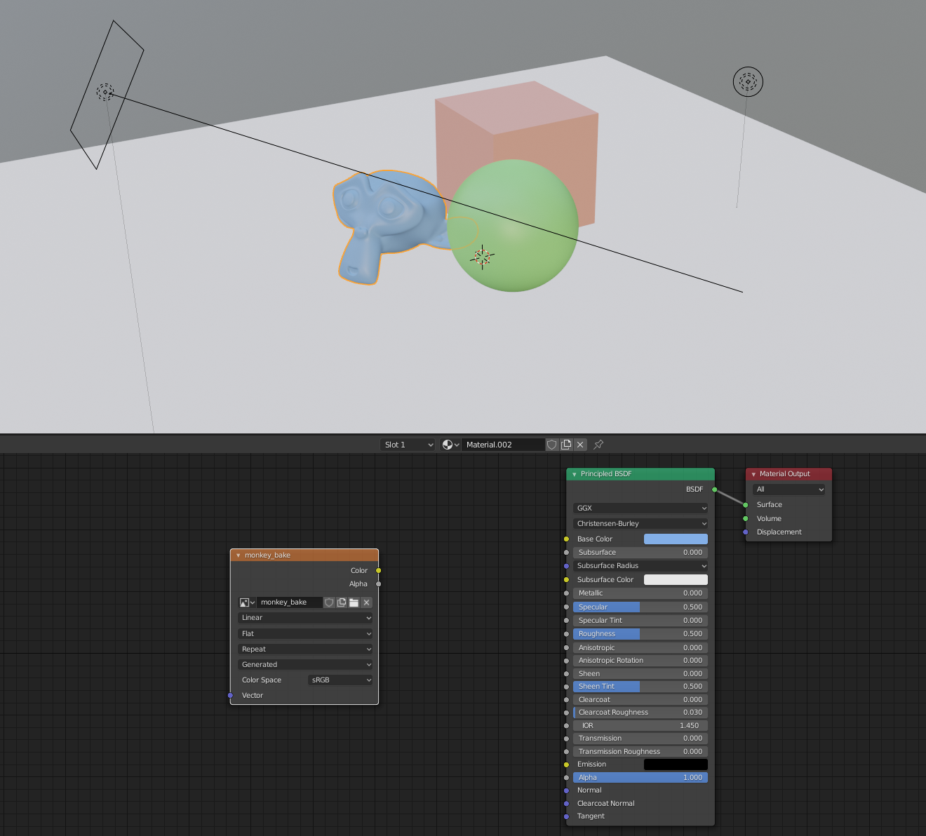
9.The next step is to connect each of the textures with the target object.
This is done in the shader editor.
Go to the Shading tab.
Select the object which should be connected to a texture so that its material nodes are revealed in the bottom panel.
With the mouse hovering over this material node panel, press Shift + A to show the menu for new nodes.
Select Texture > Image Texture to add an image texture node.
10.Do not connect the image texture node to anything, otherwise there will be recursive issues in the baking process where Blender tries to evaluate the texture for the material and writes on it at the same time. Instead, go to the small dropdown on the Image Texture node next to the ”+ New” button and select the texture that you just created for the object. Repeat this step for every object.
11.Click on the tab with the camera icon in the inspector on the right to open the render settings. We need to set the quality settings for the bake to avoid a grainy bake. Expand the first section which is called “Sampling”. It determines how many rays the render engine casts into the scene. This value also applies to baking processes. In general, higher values mean that the result will be less grainy since the brightness values of more rays can be averaged. The downside is that the additional rays need to be calculated which increases bake times. For the given example, a value of 1024 works well.
12.We are now ready to bake. Select the object which should be baked. The baking process will write on the image texture which is selected in the node setup. Hence, make sure that the image node with the created texture is actually selected. Expand the third-to-last section in the inspector. It is called “Bake”. Make sure that the bake type is set to Combined and that everything is checked underneath Influence. Click the button “Bake”. The baking process will take a bit of time. The progress can be seen at the bottom of the panels in a small progress bar. Once the baking process has finished, the result can be inspected in the Image Editor.
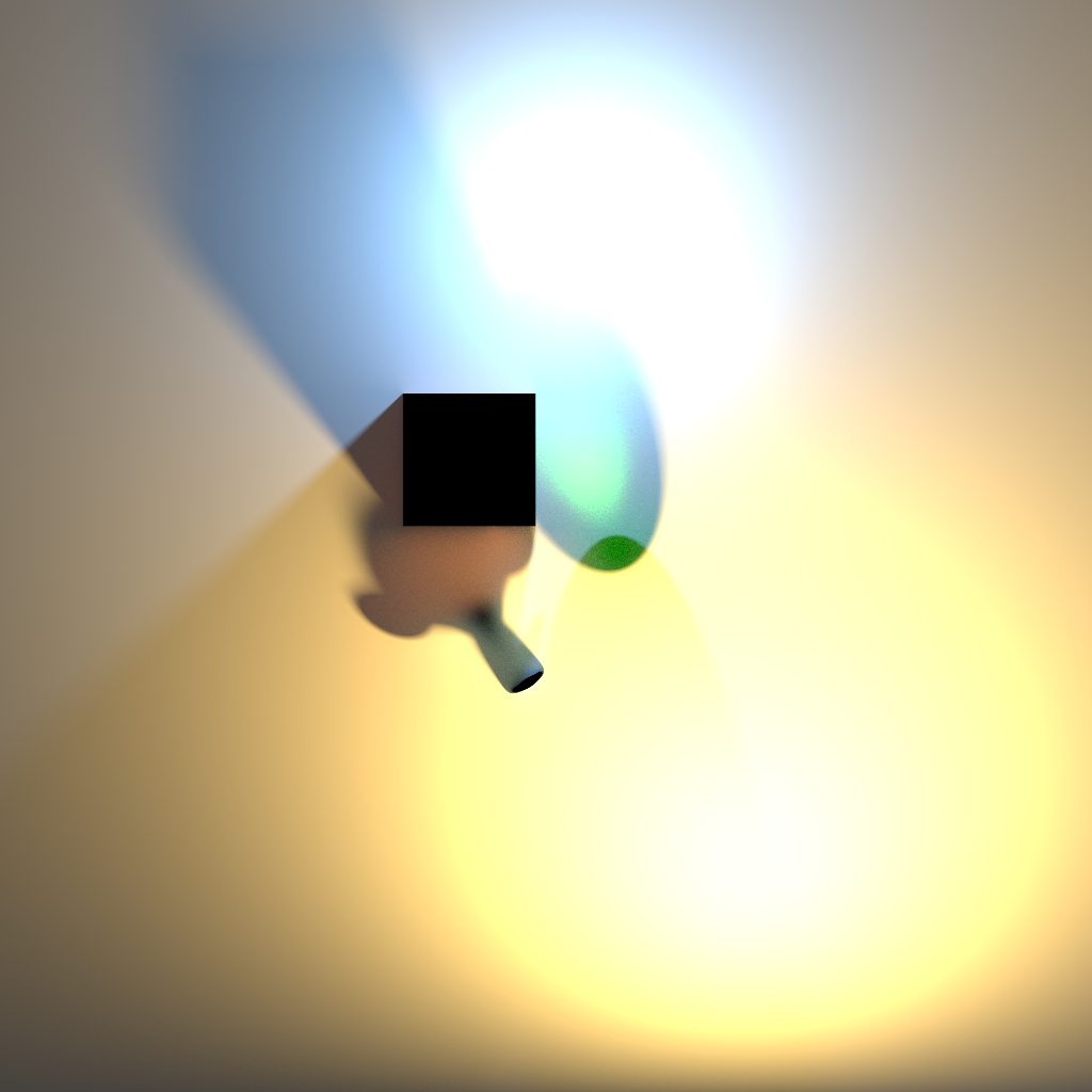
13.It is important to know that despite the fact that the texture is visible in the Image Editor, it has not yet been saved. If you close the Blender file now, the texture will be lost. Hence, go to the top menu of the Image Editor and select Image > Save As… to save the image.
14.Repeat the baking steps for all objects that you prepared for the baking process.