 Computer Graphics
Contents
Geometry Representation of Objects
Objects that we know in everyday life are all three-dimensional. In order to define the shape of such objects, a representation is required that can be processed by the computer to show the object on a screen. One way to represent an object is using polygonal meshes. Other options include point clouds, constructive solid geometry and volumetric representations.
Polygonal Meshes
A mesh is an undirected graph which approximates the surface of an object. It consists of individual vertices which are situated at defined points in 3D. The vertices can be connected with an edge between them. Vertices and edges form faces, which are visible as a surface in a rendered image.
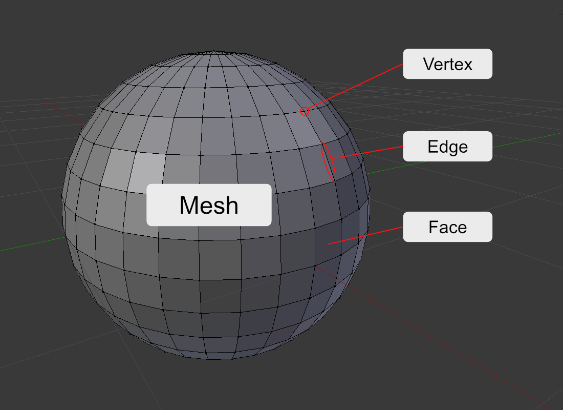
A face is a polygon since it can have any number of vertices. For geometry, triangular faces are preferred as they are guaranteed to be convex and all three vertices form are part of the same plane. In contrast to this, a quad with four vertices can be concave and the vertices are not guaranteed to be positioned in the same plane.
Quad topology is preferred for manual modeling as it is more manageable. Modellers can create strips from a series of quads that follow the object’s curvature and can be subdivided further to add more detail.
Point Clouds
Point clouds consist of isolated points in the 3D space. Usually, each point resembles a point on the surface of an object. Such a result can e.g. be created by 3D scanners which scan the surface of an object and place singular measure points. Since the points do not form a closed surface, they are usually converted to a polygonal mesh in a post-processing step. However, there are also methods that directly depict the point cloud render as a closed surface (Botsch et al., 2002).
Constructive Solid Geometry
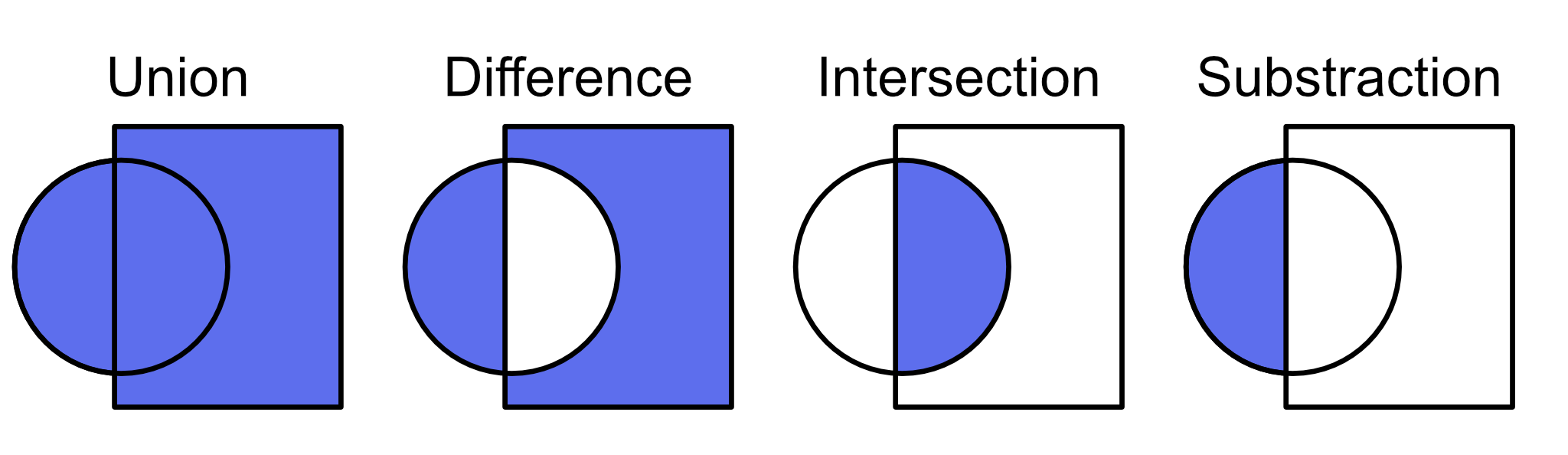
In Constructive Solid Geometry (CSG), 3D objects are represented as a composition of primitive geometric shapes like spheres, cubes, etc. (Rossignac, 1987). The shapes are combined using Boolean operations. Each primitive shape can be described exactly using mathematical formulas. This means that for every point in space, one can decide if it part of a shape or not. By processing the Boolean operations, objects can be created that have a perfectly smooth curvature. This is an advantage compared to polygonal meshes since they can only approximate curvatures using a finite number of vertices. For this reason, CSG is preferred, e.g. for creating exact 3D models of cars
Volumes
3D structures can also be represented as volume data. This means that there is a 3D data set that is usually rasterized into a voxel grid. Each voxel contains a density value that describes how dense the object is at this position.
The purpose of such representations is usually to visualize the internal structure of the volume that is underneath the surface. For instance, volume representations are produces by MRT scans in medicine. To create 2D images that can be shown on a screen, it makes sense to use methods that can visualize the internals of an object. This is e.g. done by ray casting.
There are also methods such as the marching cubes algorithm which allows the conversion of volumes into polygonal meshes.
Rendering Pipeline
The term rendering describes the process which transforms a definition of a 3D space into a 2D image which can be shown on the screen. There are different rendering pipelines for the aforementioned geometry representations. In general, they follow the same principle by starting with the geometry, apply transformations to them and rasterize geometry to show it on the screen, calculate surface information regarding lighting and the object’s colour and compose an image out of this.
Mesh Rendering Pipeline
The rendering pipeline for polygonal meshes starts with the 3D geometry that is represented as the mesh. To this geometry, 3D transformations are applied to position it in the scene. After that, a perspective transformation is applied which transforms the geometry to an orthogonal space based on a view frustum. The perspective transformation bakes the perspective foreshortening into the geometry. Then, geometry which is outside of the view frustum is clipped so that successive steps are only applied for geometry which actually has the chance to be visible. A rasterization step transfers the geometry to fragments, which are possible candidates for pixels on the screen. The next two steps determine the shading of the object’s surface. They calculate lighting information and apply texture data to the fragments. Finally, a visibility test is performed which makes sure that for overlapping geometry only the object in front is rendered. The final result is the image.